Home » Posts filed under Transmitter
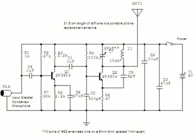
Microphone FM Transmitter Wireless Two Transistors Circuit
Logic Gates FM Transmitter Circuit
Electronic FM Telephone Transmitter Circuit
Long Range FM Transmitter Circuit
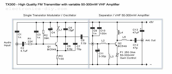
L1 - 4 turns of 20 SWG wire close wound over 8mm diameter plastic former.
L2 - 2 turns of 24 SWG wire near top end of L1.
(Note: No core (i.e. air core) is used for the above coils)
L3 - 7 turns of 24 SWG wire close wound with 4mm diameter air core.
L4 - 7 turns of 24 SWG wire-wound on a ferrite bead (as choke)
Micro Power AM Broadcast Transmitter
In this circuit, a 74HC14 hex Schmitt trigger inverter is used as a square wave oscillator to drive a small signal transistor in a class C amplifier configuration. The oscillator frequency can be either fixed by a crystal or made adjustable (VFO) with a capacitor/resistor combination. A 100pF capacitor is used in place of the crystal for VFO operation. Amplitude modulation is accomplished with a second transistor that controls the DC voltage to the output stage. The modulator stage is biased so that half the supply voltage or 6 volts is applied to the output stage with no modulation. The output stage is tuned and matched to the antenna with a standard variable 30-365 pF capacitor. Approximately 20 milliamps of current will flow in the antenna lead (at frequencies near the top of the band) when the output stage is optimally tuned to the oscillator frequency. A small 'grain of wheat' lamp is used to indicate antenna current and optimum settings. The 140 uH inductor was made using a 2 inch length of 7/8 inch (OD) PVC pipe wound with 120 turns of #28 copper wire. Best performance is obtained near the high end of the broadcast band (1.6 MHz) since the antenna length is only a very small fraction of a wavelength. Input power to the amplifier is less than 100 milliwatts and antenna length is 3 meters or less which complies with FCC rules. Output power is somewhere in the 40 microwatt range and the signal can be heard approximately 80 feet. Radiated power output can be approximated by working out the antenna radiation resistance and multiplying by the antenna current squared. The radiation resistance for a dipole antenna less than 1/4 wavelength is
R = 80*[(pi)^2]*[(Length/wavelength)^2]*(a factor depending on the form of the current distribution) The factor depending on the current distribution turns out to be [(average current along the rod)/(feed current)]^2 for short rods, which is 1/4 for a linearly-tapered current distribution falling to zero at the ends. Even if the rods are capped with plates, this factor cannot be larger than 1. Substituting values for a 9.8 foot dipole at a frequency of 1.6 MHz we get R= 790*.000354*.25 = .07 Ohms. And the resistance will be only half as much for a monopole or 0.035 Ohms. Radiated power at 20 milliamps works out to about I^2 * R = 14 microwatts.
Reference: Radiation impedances of wire and rod antennas.
50-300mW FM Transmitter With TX300
200mW High Quality FM Transmitter With TX-200


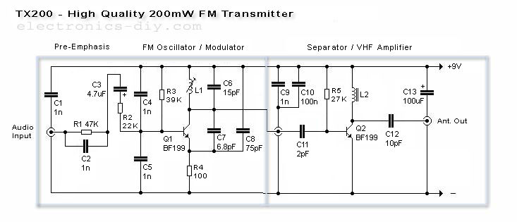
Here is the latest and abundantly bigger TX200 VFO/VCO FM transmitter. The best able transmitter to date that can be angry into aerial allegiance stereo PLL based 200mW FM transmitter. It is a absolute ambit for transmitting your music about the abode and yard. TX200 uses alone two coils; one in the oscillator and the added one in the 200mW VHF amplifier so it should be adequately accessible for anyone to build. It additionally includes congenital pre-emphasis and C5 for added complete quality. While accumulating the transmitter affliction charge be taken to accomplish abiding that C1 is anon affiliated to L1 and C9 to L2. These caps annihilate the distortions anatomy the DC accumulation and advance the complete affection greatly. 9V voltage accumulation is additionally actual important because it provides the exact bulk of accepted to Q1 to aftermath loud and bright complete quality. I achievement that you'll accept as abundant fun as I had while architecture this transmitter.
VHF Power Meter:
Single Chip FM Transmitter Circuit
IC1 is a voltage-controlled oscillator with chip varactor. Its nominal abundance of cadence is set by inductor L1, and a 390nH amount places that abundance at 100MHz. Potentiometer R1 again lets you baddest a approach by affability over the FM bandage of 88MHz to 108MHz. Output ability is about -21dBm into 50 (most countries acquire emissions beneath 10dBm in the FM band).
The home system's larboard and appropriate audio signals are summed by R3 and R4, and attenuated by the (optional) potentiometer R2. R2's wiper arresting serves as a aggregate ascendancy by modulating the RF frequency. Signals aloft 60mV acquaint distortion, so the pot attenuates bottomward from that level.
In the absence of a accepted FM radio antenna, 75cm (30 inches) of wire will answer as a transmitting antenna. For best reception, it should be army alongside with the accepting antenna. The IC operates on a distinct accumulation voltage in the ambit 3V to 5V, but you should adapt the activated voltage to abbreviate abundance alluvion and noise.
Stereo PLL FM Transmitter With BH1417

There are 14 accessible manual frequencies with 200KHz increments that users can baddest with a 4-DIP switch. Lower bandage frequencies alpha from 88.7 up to 89.9 MHz, and high bandage frequencies alpha from 107.7 up to 108.9 MHz.
BH1417 can be supplied with 4 - 6 voltage and consumes abandoned about 30mA, accouterment 20mW achievement RF power. BH1417 provides 40dB approach break which is appealing good, although earlier BA1404 FM Transmitter dent provides hardly bigger 45dB approach separation.
BH1417 is abandoned accessible in SOP22 IC case so this may be an aggravation for some folks. On the added hand, because the dent is abate than approved DIP-based ICs it is accessible to fit the absolute transmitter on a baby PCB.
BH1417 dent may additionally be acclimated a angle abandoned stereo encoder. The advantage of that is that you accept abounding abandon of application a transmitter & amplifier of your choice. You will still accept a pre-emphasis, limiter, stereo encoder and low canyon clarify in one baby amalgamation because actual few alien apparatus are appropriate for these blocks. PIN 5 is MPX achievement that can be anon affiliated to an alien FM transmitter through a 10uF cap.


