Showing posts with label Battery. Show all posts

NiMH Battery Charger Circuit


Nickel Metal Hydride battery that demands present regulated charging. The charger offers 140 mA current for quick charging of the battery.Power provide part consists of a 0-18 volt AC one Ampere step-down transformer, a full wave bridge rectifier comprising D1 through D4 along with the smoothing capacitor C1. Current regulation is accomplished from the action of R1,R2 as well as the Epitaxial Darlington PNP transistor Tip 127. Resistor R1 retains the charging current to 140 milli amperes. LED and resistor R2 plays an significant role to manage the base current of T1 and therefore its output. Around 2.6 volts drop develops across the LED which seems in the base of T1. Emitter - base junction of T1 drops about 1.two volts. So two.6 - 1.2 volts offers 1.40 volts. Therefore the current passing by means of R1 are going to be 1.40 V / ten = 0.14 Amps or 140 Milli Amps. The LED act because the charging status indicator. LED lights only when the battery is connected to the output of circuit and the input voltage is regular.
Read MoreNiMH Battery Charger Circuit

Motorcycle and Car Battery Tester Circuit
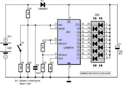

Motorcycle and Car Battery Tester Circuit

Going camping nowadays involves demography lots of cyberbanking accessories whether for day to day active or for fun and entertainment. Most of the time a answerable advance acerbic array and a ability inverter would be acclimated to ensure a calmly organized anniversary area alluringly the adult and the accouchement affably use their electric and cyberbanking gear! With rechargeable lead-acid batteries it’s consistently advantageous - if not capital - to actuate whether the ability antecedent you’re carriage forth on your campaign is accident accommodation and needs to be topped up. The aforementioned ambit would additionally appear in accessible back activity on a car or motorbike cruise as it can analysis the cachet of a 12 V (car) or a 6 V (motorcycle) battery. Although the ambit draws so little ability that it will not acutely amount the array beneath test, it should not be larboard affiliated permanently. The ambit employs the accustomed LM3914 (IC1) to affectation the voltage level. The LED readout creates a array cachet readout: back the top LED lights, the array is absolutely charged. Back the basal LED lights, the array needs approaching charging! Switch S1 selects amid 12 V and 6 V operation. A alternation diode, D1, protects the bargraph disciplinarian from about-face accumulation voltage. A color-coded affectation with alone LEDs could be acclimated instead of the common-anode bargraph affectation for bigger adumbration of the accompaniment of the battery.

Via: extremecircuits.net
Read MoreMotorcycle and Car Battery Tester Circuit

Cell Phone Battery Meter 3.6 Volt


3.6 Volt cell phone battery meter


This is a similar circuit to the above and provides a 4 LED bar graph indicating the voltage of a common 3.6 volt Lithium - Ion recharable cell phone battery. The reference voltage is provided by a TL431 programmable voltage source which is set to 3.9 volts where the TL431 connects to the 1K resistor. The lower reference for the LED at pin 14 is set with the 5K adjustable resistor.

The programmed voltage of the TL431 is worked out with a voltage divider (10K 5.6K). The adjustment terminal or junction of the two resistors is always 2.5 volts. So, if we use a 10K resistor from the adjustment terminal to ground, the resistor current will be 2.5/10000 = 250uA. This same current flows through the upper resistor (5.6K) and produces a voltage drop of .00025 * 5600 = 1.4 volts. So the shunt regulated output voltage at the cathode of the TL431 will be 2.5 + 1.4, or 3.9 volts.

Working out the LED voltages, there are three 390 ohm resistors in series with another adjustable (5K) resistor at the bottom. Assuming the bottom resistor is set to 2K ohms, the total resistance is 390+390+390+2000 = 3170 ohms. So, the resistor current is the reference voltage (3.9) divided by the total resistance, or about 3.9/ (390 + 390 + 390 + 2000) equals 1.23 mA. This gives us about .00123*2000= 2.46 volts for the bottom LED, and about .00123*390 = .48 volts for each step above the bottom. So, the LEDs should light at steps of 2.46, 2.94, 3.42, and 3.9. A fully charged cell phone battery is about 4.2 volts. You can adjust the 5.6K resistor to set the top voltage higher or lower, and adjust the lower 5K resistor to set the bottom LED for the lowest voltage. But you do need a 6 to 12 volt or greater battery to power the circuit.


Read MoreCell Phone Battery Meter 3.6 Volt

Battery Booster Circuit


The inspiration for this design came from the author’s experience with a mini model helicopter (from Silverlit). This particular model has a hand-held transmitter powered by six AA batteries which acts as a charging station in between flights to recharge the helicopter’s LiPo battery.


Even alkaline batteries become discharged relatively quickly because of the energy demands of the helicopter. Replacing the alkaline cells with six rechargeable NiMH batteries brought its own problems; the cell voltage is around 1.4 V after recharging but this quickly levels-out to 1.2 V once you begin drawing energy and this proved to be too low to recharge the helicopter battery. What is needed here is a voltage converter design small enough to fit into the space taken up by an AA battery which pumps up the voltage from the (now five rechargeable cells) up to the level produced by six alkaline batteries.

The author was not satisfied with the most simple design solution to the problem; it would be more useful if this booster cell could be used in any battery compartment irrespective of the number of cells. The number of batteries (n) would then be replaced by n–1 rechargeable cells (with one cell position taken up by the booster) giving an output voltage the same as if n primary cells were fitted.

The circuit described here can be used in applications requiring four to ten primary cells. With the booster fitted, only three to nine rechargeable cells would be required. The use of (more bulky) electrolytic capacitors with a 35 V rating would allow the booster to be used in applications of up to 20 batteries.


In principle almost any switching regulator IC can be used in this way. The power output from this circuit with a LT1172 regulator is around 500 mA but it can be increased to 2 A for example by using the LT1170 instead.

G4QV8UHSPHF9

Read MoreBattery Booster Circuit