
Nickel Metal Hydride battery that demands present regulated charging. The charger offers 140 mA current for quick charging of the battery.Power provide part consists of a 0-18 volt AC one Ampere step-down transformer, a full wave bridge rectifier comprising D1 through D4 along with the smoothing capacitor C1. Current regulation is accomplished from the action of R1,R2 as well as the Epitaxial Darlington PNP transistor Tip 127. Resistor R1 retains the charging current to 140 milli amperes. LED and resistor R2 plays an significant role to manage the base current of T1 and therefore its output. Around 2.6 volts drop develops across the LED which seems in the base of T1. Emitter - base junction of T1 drops about 1.two volts. So two.6 - 1.2 volts offers 1.40 volts. Therefore the current passing by means of R1 are going to be 1.40 V / ten = 0.14 Amps or 140 Milli Amps. The LED act because the charging status indicator. LED lights only when the battery is connected to the output of circuit and the input voltage is regular.
Showing posts with label Charger. Show all posts
Showing posts with label Charger. Show all posts
iPod Charger Simple Circuit Diagram
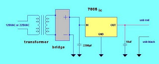
This DIY simple iPod Charger Project aims to give simple idea on how to build you IPod charger and explain in details the materials needed and their functions. This page will serve as a guide on constructing the charger. Schematic diagram of the is shown below. The IPod charger circuit is composed of an AC to DC converter and a voltage regulator.

Requirements of a good iPod charger
For the iPod battery to be charged well and safely, we must come up to a battery charger design that is similar to commercial IPod charger specifications. The charger output voltage is about 5V of about maximum current of 800mA

Charger materials and their functions
Transformer (step down) - is used to step down the voltage from an input voltage of 220VAC to 12VAC output or you can use 120VAC to 12VAC if you have 120V main source. Transformer is rated 5VA
7805 regulator IC -7805 regulator IC that will maintain the voltage output to 5V for good and safe charging of IPod battery. You can use any voltage 5V regulator IC that is available.

Diode Bridge or Rectifier Diode – this is where the conversion of Alternating Current (AC) voltage to Direct Current (DC) takes place. DC voltage is needed for battery charging.The bridge diode must be rated 1A.You can chose any of the rectifier below.

W02M- 1.5A 100V Bridge Rectifier

1N4001 -1A 50V
or any diode of the same specs
Capacitor –It minimize fluctuating voltage (ripple voltage) coming from the bridge rectifier. Provides better voltage regulation in the charger

2200uF 25V capacitor or higher

10uF 10V capacitor or higher
Female end of USB connector- is where the charger cord is connected and the IPod is charged. Use only the RED (1) and BLACK (4) for the charger circuit.

pin 1 red -is connected to the positive output of IPod charger (5V)
pin2 white- data wire, no connection
pin3 green- data wire, no connection
pin 4 black -is connected to ground or negative output of Ipod charger
pin2 white- data wire, no connection
pin3 green- data wire, no connection
pin 4 black -is connected to ground or negative output of Ipod charger

use only pin 1 and pin 4 for this charger
Miscellaneous charger accessories
Wires
Cutter for cutting wires
Voltmeter for testing the output
Steps in IPod charger construction
1. Prepare the needed materials
2. Assemble the circuit by following the circuit diagram
3. Test the charger output voltage by a voltmeter-It must be 5V DC
Via: electronician.blogspot.com
Lithium Ion Charger 2 Cell
2 Cell Lithium Ion Charger
This circuit was build to charge a couple series Lithium cells (3.6 volts each, 1 Amp Hour capacity) installed in a portable transistor radio.
The charger operates by supplying a short current pulse through a series resistor and then monitoring the battery voltage to determine if another pulse is required. The current can be adjusted by changing the series resistor or adjusting the input voltage. When the battery is low, the current pulses are spaced close together so that a somewhat constant current is present. As the batteries reach full charge, the pulses are spaced farther apart and the full charge condition is indicated by the LED blinking at a slower rate.
A TL431, band gap voltage reference (2.5 volts) is used on pin 6 of the comparator so that the comparator output will switch low, triggering the 555 timer when the voltage at pin 7 is less than 2.5 volts. The 555 output turns on the 2 transistors and the batteries charge for about 30 milliseconds. When the charge pulse ends, the battery voltage is measured and divided down by the combination 20K, 8.2K and 620 ohm resistors so that when the battery voltage reaches 8.2 volts, the input at pin 7 of the comparator will rise slightly above 2.5 volts and the circuit will stop charging.
The circuit could be used to charge other types of batteries such as Ni-Cad, NiMh or lead acid, but the shut-off voltage will need to be adjusted by changing the 8.2K and 620 ohm resistors so that the input to the comparator remains at 2.5 volts when the terminal battery voltage is reached.
For example, to charge a 6 volt lead acid battery to a limit of 7 volts, the current through the 20K resistor will be (7-2.5)/ 20K = 225 microamps. This means the combination of the other 2 resistors (8.2K and 620) must be R=E/I = 2.5/ 225 uA = 11,111 ohms. But this is not a standard value, so you could use a 10K in series with a 1.1K, or some other values that total 11.11K
Be careful not to overcharge the batteries. I would recommend using a large capacitor in place of the battery to test the circuit and verify it shuts off at the correct voltage. 
NiCad Batteries Charger

NiCAD batteries have a capacity specification called milliamp-hours. This value called "C" is a measure of how much total current they can provide in one hour. Milliamp-hours is another way to express the energy contained in the battery. To recharge a NiCAD battery conservatively, it is common practice to pump a current of 0.1 C into the anode or positive terminal for about 12 hours. Therefore, if you had a D-size NiCAD with a capacity of 4000mAh, you would want to charge it at 400mA for about 12 hours. Another advantage of this charging technique is that it is gentle on batteries and doesn't cause them to lose capacity as quickly as the fast charge techniques.
The output current of this battery charger circuit is controlled by the summation of the bandgap reference diode and the base-emitter junction of the PNP transistor. The PNP transistor provides negative feedback to the gate of the MOSFET. As noted in the schematic, the batteries being charged can have a total of 12V which is equivalent to about 8 NiCAD's in series. The output current is determined by the value of R1 which is determined by:
R1=3.2Volts/Iout
The power dissipation of R1 will equal:
Pr1=3.2Volts*Iout
Be sure to provide pleanty of heatsink for Q1 and choose an appropriately sized resistor for R1. The following table summarizes some of the resistor current combinations that are possible:
Iout Resistor Value Resistor Power
100mA 33 ohms 1 watt
500mA 6.2 ohms 2 watt
1Amp 3.3 ohms 5 watt
12V Lead Acid Battery Charger Automatic Circuit

# R2 will accept to be adapted to set the able accomplishment allegation voltage. Flooded and gel batteries are about answerable to 13.8V. If you are cycling the array (AGM or gel) again 14.5V to 14.9V is about recommended by array manufacturers. To set up the charger, set the pot to midway, about-face on the charger and again affix a array to it's output. Monitor the allegation with a voltmeter until the array alcove the able end voltage and again acclimatize the pot until the LED glows steadily. The charger has now been set. To allegation assorted array types you can arise the pot on the advanced of the case and accept anniversary position apparent for the adapted voltage.
# Q1 will allegation a heatsink. If the ambit is army in a case again a baby fan ability be all-important and can about be powered adapted off the achievement of D1.
# Q1 will allegation a heatsink. If the ambit is army in a case again a baby fan ability be all-important and can about be powered adapted off the achievement of D1.
# T1 is a agent with a primary voltage adapted to your area (120V, 220V, etc.) and a accessory about 12V. Using a college voltage accessory (16V-18V) will acquiesce you to allegation 16V batteries sometimes acclimated in antagonism applications.
# If the ambit is powered off, the array should be broken from it's achievement contrarily the ambit will cesspool the array slowly.
12V Lead Acid Battery Charger Automatic Circuit Part List:
# If the ambit is powered off, the array should be broken from it's achievement contrarily the ambit will cesspool the array slowly.
12V Lead Acid Battery Charger Automatic Circuit Part List:
| R1, R3 | 2 | 330 Ohm 1/4W Resistor | |
| R2 | 1 | 100 Ohm 1/4W Pot | |
| R4, R5, R7, R8 | 4 | 82 Ohm 2W Resistor | |
| R6 | 1 | 100 Ohm 1/4W Resistor | |
| R9 | 1 | 1K 1/4W Resistor | |
| C1 | 1 | 220uF 25V Electrolytic Capacitor | |
| D1 | 1 | P600 Diode | Any 50V 5A or greater rectifier diode |
| D2 | 1 | 1N4004 Diode | 1N4002, 1N4007 |
| D3 | 1 | 5.6V Zener Diode | |
| D4 | 1 | LED (Red, Green or Yellow) | |
| Q1 | 1 | BT136 TRIAC | |
| Q2 | 1 | BRX49 SCR | |
| T1 | 1 | 12V 4A Transformer | See Notes |
| F1 | 1 | 3A Fuse | |
| S1 | 1 | SPST Switch, 120VAC 5A | |
| MISC | 1 | Wire, Board, Heatsink For U1, Case, Binding Posts or Alligator Clips For Output, Fuse Holder |
Mobile Phone Charger Circuit For Traveling

Mobile Phone Charger Circuit For Traveling
Here is an ideal Mobile charger using 1.5 volt pen cells to charge mobile phone while traveling. It can replenish cell phone battery three or four times in places where AC power is not available. Most of the Mobile phone batteries are rated at 3.6 V/500 mA. A single pen torch cell can provide 1.5 volts and 1.5 Amps current. So if four pen cells are connected serially, it will form a battery pack with 6 volt and 1.5 Amps current. When power is applied to the circuit through S1, transistor Q1 conducts and Green LED lights.
When Q1 conducts Q2 also conducts since its base becomes negative. Charging current flows from the collector of Q1. To reduce the charging voltage to 4.7 volts, Zener diode D2 is used. The output gives 20 mA current for slow charging. If more current is required for fast charging, reduce the value of R4 to 47 ohms so that 80 mA current will be available. Output points are used to connect the charger with the mobile phone. Use suitable pins for this and connect with correct polarity. The circuit comes from here.
Parts:
R1 = 1K
R2 = 470R
R3 = 4.7K
R4 = 270R
R5 = 27R
C1 = 100uF-25V
D1 = Green LED
D2 = 4.7V/1W Zener
B1 = 1.5Vx4 Cells
S1 = On/Off Switch
Q1 = BC548
Q2 = SK100


