Showing posts with label Detector Circuit. Show all posts

One KHz Synchronous Detector Circuit


One KHz Synchronous Detector Circuit

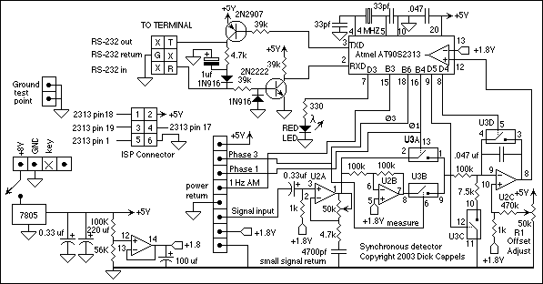
This circuit employs a synchronous demodulator to separate a 1 KHz signal from noise and measures the amplitude with the 1 kHz signals when a 2nd at about 60 microvolts per count then sends the measurements via an RS-232 interface for further processing or exhibit. An LED about the board also lights when the measured signal exceeds a preset threshold.

This experiment was began when I took an interest in getting ELF wireless signals. It also has applictions in optics and superior frequency RF, or for that matter, any place one wants to measure a small signal, of which the frequency and phase are recognized, in the presence of noise.

Using the addition of the preamplifier according to the LM324, the sensitivity of this circuit was very easily extended to a sensitivity to 160 nanovolts per count. That an LM324 is utilized with little within the way of noise about the output testifies to the worth of employing this type of detector.

The incoming signal is buffered by U2A (there is on U1 with this schematic as U1 was moved to a separate preamp assembly), which delivers a noniverted signal towards the integrator when U3A is switched on. U2B inverts the buffered signal from U2A and offers an inverted edition of the signal towards the integrator when U3B is switched on. To increase the charging fee, possibly reduce the 100k resistor around the input of U2C or decrease the .047 uf integrating capacitor. The signals fed into the integrator charge the .047 uf capacitor within the integrator. Right after 999 cycles with the 1 kHz sampling signal, U3C is turned on plus the capacitor is discharged with a continual current (one.8V/7.5K = 240 microamps), creating a linear positive-going ramp at five,106 volts/second on the output of U2C. Though the output of U2 is ramping up toward the one.eight volt reference, the AT90S2313 sits inside a loop, incrementing a counter each and every 1.25 microseconds, until the comparitor around the AT90S2313 modifications state, indicating that the ramp on U2C has reached the one.8 volt reference voltage. The optimum count for this measurement is 127 to restrict the time invested in the measurement to less than the 250 microsecond interrupt interval. Therefore, a 7 bit measurement is created in 160 microseconds or much less, and it is finished within a single 250 microsecond interrupt interval.

The charge of discharge in the integrating capacitor throughout the measurement phase is set through the present in to the node, 1.eight volts/7.five k =240 microamps, divided by the .047 uf capacitance, which offers a 5100 volt/second voltage ramp. The A/D conversion sensitivity is therefore 1.25 us/count X 5100 volts/second = 6.375 millivolts per count. Immediately after the count is completed, which happens when the pseudo 7 bit counter overflows or even the ramp reaches the 1.8 volt reference, U3C is switched off and U3D is switched on to clamp the of your integrator to the one.eight volt reference and to make sure the capacitor is discharged to a consistent state for one millisecond before beginning signal measurement once more,The entire measurement cycle requires 999 milliseconds for integration + one millisecond to clamp the capacitor to zero, for a total of one second per measurement. The gian in the integrator is ( ( Peak input Voltage/ a hundred k Ohm) X 0.999 seconds ) )/ .047 microfarads = 212.5 volts out/volt in. The sensitivity of your detector is for that reason six.375 mv/212.5 = thirty microvolts peak per count, or because peak-to-peak = 2 x peak, 60 microvolts peak-to-peak per count. Immediately after the measurement is completed, the measured worth is formatted into BCD and sent through the UART at 9600 baud, two stop bits, no parity. The transmission with the data does not happen during interrupt time. An LED is turned on by the microcontroller in the course of the integration and measurement cycle following a measurement during which the measured worth exceeded 64 decimal.
Read MoreOne KHz Synchronous Detector Circuit

Detector Components & Infrared Motion Work


How Infrared motion detector components work


Infrared Radiation_____________

Infrared radiation exists in the electromagnetic spectrum at a wavelength that is longer than visible light. It cannot be seen but it can be detected. Objects that generate heat also generate infrared radiation and those objects include animals and the human body whose radiation is strongest at a wavelength of 9.4um. Infrared in this range will not pass through many types of material that pass visible light such as ordinary window glass and plastic. However it will pass through, with some attenuation, material that is opaque to visible light such as germanium and silicon. An unprocessed silicon wafer makes a good IR window in a weatherproof enclosure for outdoor use. It also provides additional filtering for light in the visible range.

Pyroelectric Sensors_____________

The pyroelectric sensor is made of a crystalline material that generates a surface electric charge when exposed to heat in the form of infrared radiation. When the amount of radiation striking the crystal changes, the amount of charge also changes and can then be measured with a sensitive FET device built into the sensor. The sensor elements are sensitive to radiation over a wide range so a filter window is added to the TO5 package to limit detectable radiation to the 8 to 14mm range which is most sensitive to human body radiation.

Typically, the FET source terminal pin 2 connects through a pulldown resistor of about 100 K to ground and feeds into a two stage amplifier having signal conditioning circuits. The amplifier is typically bandwidth limited to below 10Hz to reject high frequency noise and is followed by a window comparator that responds to both the positive and negative transitions of the sensor output signal. A well filtered power source of from 3 to 15 volts should be connected to the FET drain terminal pin 1.

pir1.jpg (11520 bytes)

The PIR325 sensor has two sensing elements connected in a voltage bucking configuration. This arrangement cancels signals caused by vibration, temperature changes and sunlight. A body passing in front of the sensor will activate first one and then the other element whereas other sources will affect both elements simultaneously and be cancelled. The radiation source must pass across the sensor in a horizontal direction when sensor pins 1 and 2 are on a horizontal plane so that the elements are sequentially exposed to the IR source. A focusing device is usually used in front of the sensor

The figure below shows the PIR325 electrical specifications and layout in its TO5 package. Note the wide viewing angle without an external lens.

pirspec.jpg (34297 bytes)

This is a typical application circuit that drives a relay. R10 and C6 adjust the amount of time that RY1 remains energized after motion is detected. Download PDF drawing.

appckt.jpg (32281 bytes)

Fresnel Lens_____________

A Fresnel lens (pronounced Frennel) is a Plano Convex lens that has been collapsed on itself to form a flat lens that retains its optical characteristics but is much smaller in thickness and therefore has less absorption losses.

plano.jpg  (9982 bytes)

Our FL65 Fresnel lens is made of an infrared transmitting material that has an IR transmission range of 8 to 14um which is most sensitive to human body radiation. It is designed to have its grooves facing the IR sensing element so that a smooth surface is presented to the subject side of the lens which is usually the outside of an enclosure that houses the sensor.

The lens element is round with a diameter of 1 inch and has a flange that is 1.5 inches square. This flange is used for mounting the lens in a suitable frame or enclosure. Mounting can best and most easily be done with strips of Scotch tape. Silicone rubber can also be used if it overlaps the edges to form a captive mount. There is no known adhesive that will bond to the lens material.

The FL65 has a focal length of 0.65 inches from the lens to the sensing element. It has been determined by experiment to have a field of view of approximately 10 degrees when used with a PIR325 Pyroelectric sensor.

fresnel.jpg (35285 bytes)

This relatively inexpensive and easy to use Pyroelectric Sensor and Fresnel Lens can be used in a variety of science projects, robots and other useful devices.

From : www.glolab.com

Read MoreDetector Components & Infrared Motion Work