Showing posts with label Switching. Show all posts

10V Switching Regulator Using LM5007


10V Switching Regulator Using LM500710V Switching Regulator Using LM5007 Circuit Diagram

Description.

The circuit diagram shown here is of a 10V switching regulator based on the LM5007 from National Semiconductors. The LM5007 is an integrated step down switching regulator which has all necessary systems required for making a cost effective and reliable switching regulator circuit. The IC is available in MSOP-8, LLp-8 packages and has a lot of built in features like thermal shut down, under voltage lock out, duty cycle limiting, current limiting etc.

The output voltage of this regulator can be adjusted using the resistor R3 and R4. For the given values of R3 and R4 in the circuit diagram, the output voltage will be 10V. The equation governing the output voltage is Vout = 2.5 x (R3+R4)/R4. Resistor R1 sets the switch on time and C4 is the boost boot strap capacitor. Resistor R2 determines the variation of OFF time and C3 is a decoupling capacitor.

Notes.

* The supply voltage can be anything between 12 to 72V DC.
* Output voltage can be adjusted using R3 and R4.
* C1 and C5 are polyester capacitors.
* C1 and C2 must be rated at least 100V.
* R5 and C5 forms a filter network.
* The output current limit of LM5007 is 700mA.
Read More10V Switching Regulator Using LM5007

Automatic Headlight Brightness Switch Circuit


Driving the artery with your high-beam headlights can absolutely access your visibility, but can he a blinding hazard for added drivers. This simple ambit can be active into your headlight about-face to accommodate automated switching amid aerial and low axle headlights back there is advancing traffic. It does this by analysis the lights of that traffic. In this way, you can drive cautiously with your high-beams on after blinding added drivers.

Parts:
R1 5K 1/4W Resistor
R2, R3, R4 5K Pot
Q1 NPN Phototransistor
Q2 2N3906 PNP Transistor
K1 Low Current 12V SPST Relay
K2 High Current 12V SPDT Relay
S1 SPST Switch
B1 Car Battery
MISC Case, wire, board, knobs for pots

Notes:
1. Q1 should me mounted in such a way so it points toward the front of the car with a clear line of site. Suitable places are on the dashboard, in the front grill, etc.
2. Adjust all the pots for proper response by testing on a deserted road.
3. S1 enables and disables the circuit.
4. B1 is, obviously, in the car already.
5. Before you try to connect this circuit, get a wiring diagram for your car. Some auto manufacturers do weird things with wiring.
6. Connection A goes to the high beam circuit, B goes to the headlight switch common and C connects to the low beam circuit.


author:
e-mail:
web site: http://www.aaroncake.net
Read MoreAutomatic Headlight Brightness Switch Circuit

Switching Supply In Telephone Ring Generator


Telephone Ring Generator Using Switching Supply

The telephone ring generator shown below generates the needed high voltage from a simple switching mode power supply (SMPS) which employs a CMOS Schmitt Trigger square wave oscillator, 10 mH inductor, high voltage switching transistor (TIP47 or other high voltage, 1 amp transistor) and a driver transistor (2N3053). The inductor should have a low DC resistance of 1.5 ohms or less. The switching supply must have a load connected to prevent the voltage from rising too high, so a 22K resistor is used across the output which limits the voltage to about 120 DC with the phone ringer disconnected and about 90 volts DC connected. The output voltage can be adjusted by changing the value of the 150K resistor between pins 10 and 11 which will alter the oscillator frequency (frequency is around 800 Hz as shown). The supply is gated on and off by a second Schmitt Trigger oscillator (pins 12/13) so that the phone rings for about 2 seconds and then the circuit idles for about a minute between rings. These times can be adjusted with the 10K and 300K resistors connected to pin 12. The push button shown is used to manually ring the phone. The 25Hz ringing frequency is generated by another Schmitt Trigger oscillator (pins 1/2) which controls the H bridge transistor output circuit. The 6 transistors in the output stage (4 NPN, 2 PNP) should be high voltage types rated at 200 volts collector to emitter or more. The ringer will only draw around 10 mA, so the output transistors can have a low current rating but must have a high voltage rating. I used TIP47s and small signal PNPs of unknown numbers that I had on hand, but other types such as NTE287 (NPN) and NTE288 (PNP) should work. Both have a 300 volt C-E rating and cost about $0.95 from mail order houses.

The two 470 ohm resistors connected to the output serve to limit the current in case the output is shorted. I never tried shorting the output to see how effective the resistors are, but I did lose a couple transistors and then decided to add the resistors. They should limit the surge to around 120 mA which should be low enough to prevent damage. The circuit draws around 250 mA when the ring signal is present so if you want to operate it from batteries, six 'D' type alkaline cells are recommended. It probably won't work with a small 9 volt battery.

Read MoreSwitching Supply In Telephone Ring Generator

CMOS Simple Touch Switch Circuit


CMOS Simple Touch Switch Circuit

Similar to the CMOS based Blow About-face additionally on this site, this transistor based blow about-face can actuate a amount artlessly by the user affecting a metal plate. It is advised to anon about-face a broadcast to acquiesce it to be acclimated with ample loads. As it uses alone a few frequently accessible transistors and a 12V supply, it is ideal for adverse environments area automated switches would be damaged. Using a latching broadcast and two of these circuits, a simple two pad "touch on/touch off" adjustment can be made.

# The blow pad can be best calmly fabricated by acid a baby aboveboard of PCB actual and again soldering on a distinct wire. Alternatively, article like a penny alert to a artificial abetment will do the job.

# As mentioned, a latching broadcast can be acclimated so that a cursory blow activates the broadcast and it charcoal active. To about-face off a latching relay, ability charge be interrupted. So a 2nd ambit with a accustomed broadcast can be acclimated to cut ability (use the NC contacts on the 2nd circuit). Placed ancillary by side, two blow pads anatomy an "on" and an "off" pad.

CMOS Simple Touch Switch Circuit Part List:

Part
Total Qty.
Description
Substitutions
R1110 Meg 1/4W Resistor
R2147K 1/4W Resistor
R31120k 1/4W Resistor
R41470 Ohm 1/4W Resistor
C1115uF Electrolytic Capacitor
D111N4007 Silicon Rectifier Diode
Q112N5458 N Channel Field Effect Transistor
Q212N2222 NPN Transistor2N3904
Q312N3906 PNP Transistor
K11Relay w/12V Coil, Contacts To Suit Application
MISC1Board, Wire, Small Metal Pad For Touch Pad

Read MoreCMOS Simple Touch Switch Circuit

DC Motor Control Circuit


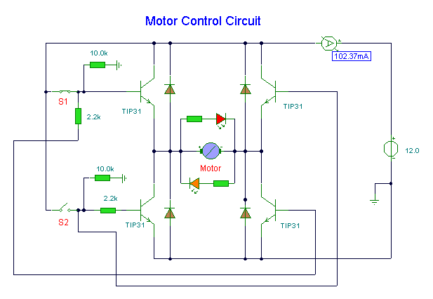
DC Motor Control CircuitDC Motor Control Circuit


Description
This circuit uses solid state switching (transistors) to control direction of a DC motor. You have precise control of the movement of the motor, and an indication of direction provided by LED's.

Circuit Notes:
Switches S1 and S2 are normally open push to make, press button switches. The LED's serve to indicate direction and may be any colour. You may need to alter the TIP31 transistors depending on the motor being used. Remember, running under load draws more current. This circuit was built to operate a small motor used for opening and closing a pair of curtains. This circuit allows manual control of the motor (and for curtain control) allows precise amounts of light into a room.

The four diodes surriunding the motor, are back EMF diodes. They are chosen to suit the motor. For a 12V motor drawing 1amp under load, I use 1N4001 diodes.

Via
Read MoreDC Motor Control Circuit