Showing posts with label Audio Circuit. Show all posts

LM3886 Power Amplifier 68W


The LM3886 is a high-performance audio power amplifier capable of delivering 68W of continuous average power to a 4 load and 38W into 8 with 0.1% THD+N from 20Hz-20kHz.

features:
Maximum Output Power : 68W RMS - 108W Peak
THD : %0.03 at 60W
SNR : 110dB at 60 W - 92.5dB at 1W
PSRR : 120dB
Protection Circuitries : DC /AC Short circuit protection and thermal protection
Output Class : Conjugate AB-A

The performance of the LM3886, utilizing its Self Peak Instantaneous Temperature (°Ke) (SPiKe™) protection circuitry, puts it in a class above discrete and hybrid amplifiers by providing an inherently, dynamically protected Safe Operating Area (SOA). SPiKe protection means that these parts are completely safeguarded at the output against overvoltage, undervoltage, overloads, including shorts to the supplies, thermal runaway, and instantaneous temperature peaks.

The LM3886 maintains an excellent signal-to-noise ratio of greater than 92dB with a typical low noise floor of 2.0µV. It exhibits extremely low THD+N values of 0.03% at the rated output into the rated load over the audio spectrum, and provides excellent linearity with an IMD (SMPTE) typical rating of 0.004%.

[source]
Read MoreLM3886 Power Amplifier 68W

Mosfet Audio Amplifier 20W


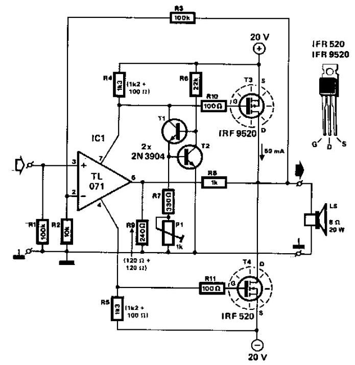
Mosfet Audio Amplifier 20W

This audio power amplifier makes use of two complementary MOSFETs (IRF9520 and IRF520) to supply up to 20W into eight O speaker. A TL071 op amp is utilized as an input amplifier. The MOSFETs should certainly be heatsinked having a heatsink of far better than 50C/W capability. THD is less than 0.15% from 100Hz to 10KHz.
Read MoreMosfet Audio Amplifier 20W

Graphic Equalizer Schematic 10 band Mono


Graphic Equalizer Schematic 10 band Mono

This really is ten band graphic equalizer for 1 channel (mono) audio program. You will need build 2 similiar circuits for 2 channel (stereo) audio method. This equalizer construct depending on TL074 low sound JFET op-amp that will give you top quality audio output.

Graphic Equalizer Schematic 10 band Mono Part List:


R1....20= 10Kohms C4= 10nF polyester C18= 68pF polysterine
R21....40= 1Mohms C5= 47nF polyester C19= 360pF polysterine
R41= 10Kohms C6= 4.7nF polyester C20= 36pF polysterine
R42= 1Kohms C7= 22nF polyester C21= 4.7uF polyester
R43.....52= 2.2Kohms C8= 2.2nF polyester C22-23= 33pF polysterine
R53.....62= 47Kohms C9= 12nF polyester C24= 10uF 25V
R63-64-66-67= 47Kohms C10= 1.2nF polyester C25-26= 47uF 25V
R65= 10Kohms C11= 5.6nF polyester C27...32= 47nF polyester
R68-69= 47 ohms 1/2W C12= 560pF polysterine IC1...3= TL074
RV1....10= 100Kohms lin FADER C13= 2.7nF polyester S1= 2X4 SW for stereo
RV11= 10Kohms log. C14= 270pF polysterine
C1= 180nF polyester C15= 1.5nF polyester
C2= 18nF polyester C16= 150pF polysterine
C3= 100nF polyester C17= 680pF polysterine
Read MoreGraphic Equalizer Schematic 10 band Mono

Audible Logic Probe Circuit Schematic


Audible Logic Probe Circuit Schematic Diagram

NE556 timer can be used as an indicator of static of digital logic audible terminal. Audible logic probe is useful for inspecting a part visually while we also need to check the logic state on other point far from the part. NE556 acts as an oscillator controlled by (SN74132N) and IC2 (SN7486N). Any logic transition from 0 to 1 and vice versa will be followed with audio beep, lasting at least 50 nanoseconds. LED provide visual indication. When the input logic is 1, the LED will glow.

Source : seekic.com
Read MoreAudible Logic Probe Circuit Schematic

Speaker Microphone Audio Circuit


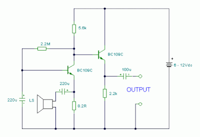
Speaker Microphone Audio Circuit

Notes:
This circuits allows you to use a cheap loudspeaker as a microphone.Sound waves reaching the speaker cone cause fluctuations in the voice coil. The voice coil moving in the speakers magnetic field will produce a small electrical signal . The circuit is designed to be used with an operating voltage between 6 and 12 volts dc. The first transistor operates in common base mode. This has the advantage of matching the low input impedance of the speaker to the common base stage, and secondly has a high voltage gain. The second stage is direct coupled and operates in emitter follower. Voltage gain is slightly less than unity, but output impedance is low, and will drive long cables.
Speech quality is not as good compared to an ordinary or ECM microphone, but quite acceptable results can be obtained. Speaker cones with diameters of 1 inch to 3 inches may be used. Speaker impedance may be 4 ohm to 64 ohm. The 8.2 ohm resistor value may be changed to match the actual speakers own impedance.

author: Andy Collinson
e-mail: anc@mitedu.freeserve.co.uk
web site: http://www.zen22142.zen.co.uk
Read MoreSpeaker Microphone Audio Circuit

80 milliwatt Improved 3 Transistor Audio Amp


This circuit is similar to the one above but uses positive feedback to get a little more amplitude to the speaker. I copied it from a small 5 transistor radio that uses a 25 ohm speaker. In the circuit above, the load resistor for the driver transistor is tied directly to the + supply. This has a disadvantage in that as the output moves positive, the drop across the 470 ohm resistor decreases which reduces the base current to the top NPN transistor. Thus the output cannot move all the way to the + supply because there wouldn't be any voltage across the 470 resistor and no base current to the NPN transistor.

This circuit corrects the problem somewhat and allows a larger voltage swing and probably more output power, but I don't know how much without doing a lot of testing. The output still won't move more than a couple volts using small transistors since the peak current won't be more than 100mA or so into a 25 ohm load. But it's an improvement over the other circuit above.

In this circuit, the 1K load resistor is tied to the speaker so that as the output moves negative, the voltage on the 1K resistor is reduced, which aids in turning off the top NPN transistor. When the output moves positive, the charge on the 470uF capacitor aids in turning on the top NPN transistor.

The original circuit in the radio used a 300 ohm resistor where the 2 diodes are shown but I changed the resistor to 2 diodes so the amp would operate on lower voltages with less distortion. The transistors shown 2n3053 and 2n2905 are just parts I used for the other circuit above and could be smaller types. Most any small transistors can be used, but they should be capable of 100mA or more current. A 2N3904 or 2N3906 are probably a little small, but would work at low volume.

The 2 diodes generate a fairly constant bias voltage as the battery drains and reduces crossover distortion. But you should take care to insure the idle current is around 10 to 20 milliamps with no signal and the output transistors do not get hot under load.

The circuit should work with a regular 8 ohm speaker, but the output power may be somewhat less. To optimize the operation, select a resistor where the 100K is shown to set the output voltage at 1/2 the supply voltage (4.5 volts). This resistor might be anything from 50K to 700K depending on the gain of the transistor used where the 3904 is shown.

Read More80 milliwatt Improved 3 Transistor Audio Amp

50 milliwatt Simple 3 Transistor Audio Amp Circuit


Here is a little audio amplifier similar to what you might find in a small transistor radio. The input stage is biased so that the supply voltage is divided equally across the two complimentary output transistors which are slightly biased in conduction by the diodes between the bases. A 3.3 ohm resistor is used in series with the emitters of the output transistors to stabilize the bias current so it doesn't change much with temperature or with different transistors and diodes. As the bias current increases, the voltage between the emitter and base decreases, thus reducing the conduction. Input impedance is about 500 ohms and voltage gain is about 5 with an 8 ohm speaker attached. The voltage swing on the speaker is about 2 volts without distorting and power output is in the 50 milliwatt range. A higher supply voltage and the addition of heat sinks to the output transistors would provide more power. Circuit draws about 30 milliamps from a 9 volt supply.

Read More50 milliwatt Simple 3 Transistor Audio Amp Circuit