Showing posts with label Regulator Circuit. Show all posts

Variable Voltage Regulator With LM317T


LM317T Variable Voltage Regulator


The LM317T is a adjustable 3 terminal positive voltage regulator capable of supplying in excess of 1.5 amps over an output range of 1.25 to 37 volts. The device also has built in current limiting and thermal shutdown which makes it essentially blow-out proof.

Output voltage is set by two resistors R1 and R2 connected as shown below. The voltage across R1 is a constant 1.25 volts and the adjustment terminal current is less than 100uA. The output voltage can be closely approximated from Vout=1.25 * (1+(R2/R1)) which ignores the adjustment terminal current ``but will be close if the current through R1 and R2 is many times greater. A minimum load of about 10mA is required, so the value for R1 can be selected to drop 1.25 volts at 10mA or 120 ohms. Something less than 120 ohms can be used to insure the minimum current is greater than 10mA. The example below shows a LM317 used as 13.6 volt regulator. The 988 ohm resistor for R2 can be obtained with a standard 910 and 75 ohm in series.

When power is shut off to the regulator the output voltage should fall faster than the input. In case it doesn't, a diode can be connected across the input/output terminals to protect the regulator from possible reverse voltages. A 1uF tantalum or 25uF electrolytic capacitor across the output improves transient response and a small 0.1uF tantalum capacitor is recommended across the input if the regulator is located an appreciable distance from the power supply filter. The power transformer should be large enough so that the regulator input voltage remains 3 volts above the output at full load, or 16.6 volts for a 13.6 volt output.
LM317 Data Sheet

Read MoreVariable Voltage Regulator With LM317T

Pass Transistor Voltage Regulator with LM317T


LM317T Voltage Regulator with Pass Transistor


The LM317T output current can be increased by using an additional power transistor to share a portion of the total current. The amount of current sharing is established with a resistor placed in series with the 317 input and a resistor placed in series with the emitter of the pass transistor. In the figure below, the pass transistor will start conducting when the LM317 current reaches about 1 amp, due to the voltage drop across the 0.7 ohm resistor. Current limiting occurs at about 2 amps for the LM317 which will drop about 1.4 volts across the 0.7 ohm resistor and produce a 700 millivolt drop across the 0.3 ohm emitter resistor. Thus the total current is limited to about 2+ (.7/.3) = 4.3 amps. The input voltage will need to be about 5.5 volts greater than the output at full load and heat dissipation at full load would be about 23 watts, so a fairly large heat sink may be needed for both the regulator and pass transistor. The filter capacitor size can be approximated from C=IT/E where I is the current, T is the half cycle time (8.33 mS at 60 Hertz), and E is the fall in voltage that will occur during one half cycle. To keep the ripple voltage below 1 volt at 4.3 amps, a 36,000 uF or greater filter capacitor is needed. The power transformer should be large enough so that the peak input voltage to the regulator remains 5.5 volts above the output at full load, or 17.5 volts for a 12 volt output. This allows for a 3 volt drop across the regulator, plus a 1.5 volt drop across the series resistor (0.7 ohm), and 1 volt of ripple produced by the filter capacitor. A larger filter capacitor will reduce the input requirements, but not much.
Read MorePass Transistor Voltage Regulator with LM317T

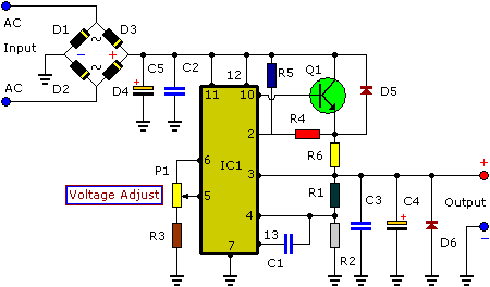
3-30V 3A Adjustable Regulated DC Power Supply


3-30V 3A Adjustable Regulated DC Power Supply

Parts list:

R1 = 8.2K
R2 = 2.2K
R3 = 680R
R4 = 1K
R5 = 82K
R6 = 0.18R/5W
C1 = 470p
C2 = 100nF-63V
C3 = 100nF-63V
C4 = 100uF-63V
C5 = 10KuF-60V
D1-D6 = 6.6A
Q1 = MJ3001 (Darligton)
IC1 = UA723D

Specifications:
  • Overload protected
  • Sshort-circuit stable
  • Output current: max. 3A
  • Output ripple voltage: 0.5mV
  • Output voltage: adjustable from 3 to 30V, stabilized
  • Input voltage: 9 to 30V AC (depending on the desired output voltage)
Assembling into a housing:
  • Depending on the transformer used, one may chose one of two housings
  • If a metal housing is used, it must be earthed for security purposes.
  • Make sure the cooling body does not touch the housing. This might cause a short circuit.
  • When mounting a toroidal transformer, it must be seen to that the fixation bolt does not touch the cover. This might cause the burning of the transformer
  • If the circuit is to be integrated into another housing, it must be provided with ventilation holes (one may make these holes oneself), necessary for the release of the heat developed.
Notes :
  1. Connect a voltage meter to the points ‘GND’ and ‘+OUT’ and adjust ‘RV1’ until the desired output voltage is reached.
  2. Apply some thermo-conducting pasta to the bottom side of the transistor and mount it on the heatsink.
  3. If you need 3-8 volt then R2 will be 5.6K
  4. If you need more than 8 volts then the R2 will be 2.2K
  5. Suitable transformer 30vAC at 120VA
From : Extremecircuits.net
Read More3-30V 3A Adjustable Regulated DC Power Supply