Showing posts with label Other Circuits. Show all posts

7-MHz Loop Antenna


[clip_image002[4].jpg]

The loop may be fed inside the center of one of the vertical sides if vertical polarization is preferred. For horizontal polarization, it can be necessary to feed either in the horizontal sides in the center. Optimum directivity happens at proper angles towards the airplane in the loop, or in much more hassle-free terms, broadside through the loop. One need to try to hang the program from on the market supports which will enable the antenna to radiate the utmost amount in some favored path.

The overall length of the wire utilized in a loop is determined in ft in the system 1005/f (MHz). Therefore, for operation at seven.125 MHz the all round wire length are going to be 141 ft. The matching transformer, an electrical 1/4 ë of 75-Ù coax cable, is often computed by dividing 246 by the operating frequency in MHz, then multiplying that amount by the velocity element from the cable becoming utilised. Therefore, foroperation at 7.125 MHz, 246/7.125 MHz = 34.53 feet. If coax with reliable polyethylene insulation is employed, a velocity issue of 0.66 have to be employed. Foam-polyethylene coax features a velocity issue of 0.eighty. Assuming RG-59 is utilised, the length of the matching transformer will become 34.53 (ft) . 0.66 = 22.79 feet, or 22 ft, 91/2 inches. This same loop antenna may well be used to the 14 and 21-MHz bands
Read More7-MHz Loop Antenna

Bent Dipole Antenna


clip_image002


The easiest way to shorten a dipole is proven in Fig . In the event you don't have sufficient duration between the supports, just hang as much of the center from the antenna as possible among the supports and let the ends hang down. The ends might be directly down or could be at an angle as indicated but in either case must be secured so that they don't move inside the wind. So long as the center portion in between the supports is at least ë/4, the radiation pattern is going to be really nearly the same as being a full-length dipole.

The resonant duration in the wire will probably be considerably shorter than a full-length dipole and may preferred be determined by experimentally adjusting the duration of ends, which might be conveniently near ground. Keep in thoughts that there can be highly great potentials at the ends of the wires and for security the ends will need to be stored from achieve.
Read MoreBent Dipole Antenna

Honda Motorcycle CB750F Wiring Diagram


Honda Motorcycle CB750F Wiring Diagram

The following picture shows the electrical wiring connection diagram for Honda Motorcycle CB750F. It shows the connection between Honda parts such as the right turn signal indicator light, oil pressure warning light, neutral indicator, high beam indicator, turn signal indicator, tachometer lights, speedometer lights, turn/signal running lights, headlight, turn signal/running light, horn and horn button, clutch switch, front stop switch, turn signal control switch, dimmer switch, engine stop switch, spark units, neutral switch, oil pressure switch, rear stop switch, fuses, ignition switch, starter motor, battery, turn signal right rear, tail and brake light, turn signal left rear, regulator/rectifier, alternator, ignition coils, pulse generator, spark plugs, and also the color code.
Read MoreHonda Motorcycle CB750F Wiring Diagram

Honda Motorcycle CB400 (Hawk II) Wiring Diagram


Honda Motorcycle CB400 (Hawk II) Wiring Diagram

The following picture shows the electrical wiring connection diagram for Honda Motorcycle CB400 (Hawk II). It shows the connection between Honda parts such as the turn signal, emergency stop switch, starter button, spark plug, capacitor discharge ignition unit, turn signal indicator, oil pressure warning light, neutral indicator, high beam warning light, speedometer light, headlight, tail light circuit, ignition switch, clutch switch, dimmer switch, horn button, oil pressure switch, horn, neutral switch, alternator, regulator rectifier, starter motor, starter magnetic switch, battery, tail and brake light, flasher relay, capacitor discharge ignition unit, and many more. Color code and diagram key also available.
Read MoreHonda Motorcycle CB400 (Hawk II) Wiring Diagram

LOW-COST HEARING AID Schematic


Skema Rangkaian LOW-COST HEARING AID Schematic

Commercially available hearing aids are quite costly. Here is an inexpensive hearing aid circuit that uses just four transistors and a few passive components. On moving power switch S to ‘on’ position, the condenser microphone detects the sound signal, which is amplified by transistors T1 and T2. Now the amplified signal passes through coupling capacitor C3 to the base of transistor T3. The signal is further amplified by pnp transistor T4 to drive a low impedance earphone. Capacitors C4 and C5 are the power supply decoupling capacitors. The circuit can be easily assembled on a small, general-purpose PCB or a Vero board. It operates off a 3V DC supply. For this, you may use two small 1.5V cells. Keep switch S to ‘off’ state when the circuit is not in use. To increase the sensitivity of the condenser microphone, house it inside a small tube. This circuit costs around Rs 65.
Read MoreLOW-COST HEARING AID Schematic

Standard Tube Lamp Disco Light Strobo Circuit


Strobo Disco Light Circuit

Using a standard fluorescent tube lamp (TL), you can make your own disco light, similar to a stroboscope light. You can even use a half-broken lamp, which one side of the heating filaments has broken. This circuit use only one side heating filament inside the tube. Look at the circuit’s schematic below. Please be aware that this circuit uses high voltage from your main power line, can be very dangerous. Although the control circuit uses 12 volt supply, it isn’t isolated from the SCR driving the high voltage. The only isolation is the audio transformer connected to your audio amplifier.

Parts List
R1: 470k; R2:100k; R3:3k9; R4:18k; R5:10k; R6:2k7; R7:33k; R8:1k; R10:2k2; R11:2k2; P1:10k; P2:10k; C1:0.1uF; C2:10uF/16V; C3:47uF/16V; TUN: 2N3904 or BC547.
Read MoreStandard Tube Lamp Disco Light Strobo Circuit

Fluorescent Lamp Circuit Driver 12vdc


Fluorescent Lamp Circuit Driver 12vdcFluorescent Lamp Circuit Driver 12vdc

A number of people have been unable to find the transformer needed for the Black Light project, so I looked around to see if I could find a fluorescent lamp driver that does not require any special components. I finally found one in Electronics Now. Here it is. It uses a normal 120 to 6V stepdown transformer in reverse to step 12V to about 350V to drive a lamp without the need to warm the filaments.

Fluorescent Lamp Circuit Driver 12vdc Parts List:

C1 - 100uf 25V Electrolytic Capacitor
C2,C3 - 0.01uf 25V Ceramic Disc Capacitor
C4 - 0.01uf 1KV Ceramic Disc Capacitor
R1 - 1K 1/4W Resistor
R2 - 2.7K 1/4W Resistor
Q1 - IRF510 MOSFET
U1 - TLC555 Timer IC
T1 - 6V 300mA Transformer
LAMP - 4W Fluorescent Lamp
MISC - Board, Wire, Heatsink For Q1

source: http://www.aaroncake.net/
Read MoreFluorescent Lamp Circuit Driver 12vdc

Automatic Electronic Emergency Light Circuit Low Cost


Automatic Electronic Emergency Light Circuit Low Cost

Description

Here is a white-LED-based emergency light that offers the following advantages:
1. It is highly bright due to the use of white LEDs.
2. The light turns on automatically when mains supply fails, and turns off when mains power resumes.
3. It has its own battery charger. When the battery is fully charged, charging stops automatically.

The circuit comprises two sections: charger power supply and LED driver.The charger power supply section is built around 3-terminal adjustable regulator (IC1) LM317, while the LED driver section is built around transistor BD140(T2). In the charger power supply section, input AC mains is stepped down by transformer to deliver 9V, 500mA to the bridge rectifier, which comprises diodes (IN4007x4). Filter capacitor (25v/1000uf)eliminates ripples. Unregulated DC voltage is fed to input pin 3 of IC1 and provides charging current through diode IN4007(D5) and limiting resistor (16ohm)R16. By adjusting preset 2.2K(VR1), the output voltage can be adjusted to deliver the required charging current. When the battery gets charged to 6.8V, zener diode conducts and charging current from regulator (IC1) finds a path through transistor BC547(T1) to ground and it stops charging of the battery. The LED driver section uses a total of twelve 10mm white LEDs. All the LEDs are connected in parallel with a 100-ohm resistor in series with each. The common-anode junction of all the twelve LEDs is connected to the collector of pnp transistor T2 and the emitter of transistor T2 is directly connected to the positive terminal of 6V battery. The unregulated DC voltage, produced at the cathode junction of Bridge(Diodes), is fed to the base of transistor T2 through a 1k resistor. When mains power is available, the base of transistor T2 remains high and T2 does not conduct. Thus LEDs are off. On the other hand, when mains fails, the base of transistor T2 becomes low and it conducts. This makes all the LEDs (LED1 through LED12) glow. The mains power supply, when available, charges the battery and keeps the LEDs off as transistor T2 remains cut-off. During mains failure, the charging section stops working and the battery supply makes the LEDs glow. Assemble the circuit on a general-purpose PCB and enclose in a cabinet with enough space for battery and switches. Mount the LEDs on the cabinet such that they light up the room. A hole in the cabinet should be drilled to connect 230V AC input for the primary of the transformer. I have tested the circuit with twelve 10mm white LEDs.You can use more LEDs provided the total current consumption does not exceed 1.5A. Driver transistor T2 can deliver up to 1.5A with proper heat-sink arrangement.

Source: Electronics Lab

Read MoreAutomatic Electronic Emergency Light Circuit Low Cost

Fluorescent Lamp Driver Circuit 12VDC


A cardinal of bodies accept been clumsy to acquisition the agent bare for the Black Light project, so I looked about to see if I could acquisition a beaming lamp disciplinarian that does not crave any appropriate components. I assuredly begin one in Electronics Now. Here it is. It uses a accustomed 120 to 6V stepdown agent in about-face to footfall 12V to about 350V to drive a lamp after the charge to balmy the filaments.

Parts:
C1 100uf 25V Electrolytic Capacitor
C2,C3 0.01uf 25V Ceramic Disc Capacitor
C4 0.01uf 1KV Ceramic Disc Capacitor
R1 1K 1/4W Resistor
R2 2.7K 1/4W Resistor
Q1 IRF510 MOSFET
U1 TLC555 Timer IC
T1 6V 300mA Transformer
LAMP 4W Fluorescent Lamp
MISC Board, Wire, Heatsink For Q1

Notes:
1. Q1 must be installed on a heat sink.
2. A 240V to 10V transformer will work better then the one in the parts list. The problem is that they are hard to find.
3. This circuit can give a nasty (but not too dangerous) shock. Be careful around the output leads.


author:
e-mail:
web site: http://www.aaroncake.net
Read MoreFluorescent Lamp Driver Circuit 12VDC

CDI Capacitor Discharge Ignition Circuit


The CDI ignition circuit produces a spark from an ignition coil by discharging a capacitor across the primary of the coil. A 2uF capacitor is charged to about 340 volts and the discharge is controlled by an SCR. A Schmitt trigger oscillator (74C14) and MOSFET (IRF510) are used to drive the low voltage side of a small (120/12 volt) power transformer and a voltage doubler arrangement is used on the high voltage side to increase the capacitor voltage to about 340 volts. A similar Schmitt trigger oscillator is used to trigger the SCR about 4 times per second. The power supply is gated off during the discharge time so that the SCR will stop conducting and return to it's blocking state. The diode connected from the 3904 to pin 9 of the 74C14 causes the power supply oscillator to stop during discharge time. The circuit draws only about 200 milliamps from a 12 volt source and delivers almost twice the normal energy of a conventional ignition circuit. High voltage from the coil is about 10KV using a 3/8 inch spark gap at normal air temperature and pressure. Spark rate can be increased to possibly 10 Hertz without losing much spark intensity, but is limited by the low frequency power transformer and duty cycle of the oscillator. For faster spark rates, a higher frequency and lower impedance supply would be required. Note that the ignition coil is not grounded and presents a shock hazard on all of it's terminals. Use CAUTION when operating the circuit. An alternate method of connecting the coil is to ground the (-) terminal and relocate the capacitor between the cathode of the rectifier diode and the positive coil terminal. The SCR is then placed between ground and the +340 volt side of the capacitor. This reduces the shock hazard and is the usual configuration in automotive applications.

Read MoreCDI Capacitor Discharge Ignition Circuit

Debounced Push Button High Current MOSFET Toggle Switch


This circuit was adapted from the "Toggle Switch Debounced Pushbutton" by John Lundgren. It is useful where the load needs to be switched on from one location and switched off from another. Any number of momentary (N/O) switches or push buttons can be connected in parallel.

The combination (10K, 10uF and diode) on the left side of the schematic insures the circuit powers up with the load turned off and the NPN transistor conducting. These components can be omitted if the initial power-on condition is not an issue.

When a switch is closed, the 1uF cap voltage is connected to the junction of the 220 ohm and 33K resistors causing the circuit to change state. When the switch is opened, the cap charges or discharges to the new level through the 1M resistor, and the circuit is ready to toggle again in about 1 second. It takes a little time for the cap to move to the new level, either +V or ground.

The (0.1uF) capacitor at the transistor base was added to supress noise that might cause false triggering if the switches are located far away from the circuit. The circuit was tested using a 12 volt, 25 watt automotive lamp, and IRFZ44. Other MOSFETs can probably be used.

Read MoreDebounced Push Button High Current MOSFET Toggle Switch

Binary Coded Decimal BCD Clock Circuit


Binary Coded Decimal (BCD) Clock


Tens of Hours

Hours


Tens of Minutes

Minutes


Tens of Seconds

Seconds

8

4

2

1


The clock circuit above uses seven ICs and 19 LEDs to indicate binary coded decimal time. The LEDs can be arranged (as shown in example above) so that each horizontal group of 3 or 4 LEDs represents a decimal digit between 0 and 9 and each individual LED represents a single bit or (binary digit) of the value. Binary digits have only two values (0 and 1) so a number written in binary would be something like 1001 or 0011, which represents decimal numbers 9 and 3 respectively. From right to left, each binary (1) represents increasing powers of 2, so that a 1 in the right hand place represents 2^0=1 and the next place to the left is 2^1=2 and then 2^2=4, and so forth. This makes binary counting fairly easy since each digit has a value of twice the one before or 1,2,4,8,16,32,64,etc. Thus the decimal value can be found by simply adding the values of each illuminated LED in the same row, (the total is shown in the box to the right). For example, the binary number 1001 would have a decimal value of 8+0+0+1 = 9. But this is actually a binary coded decimal 9 since only values from 0 to 9 are used 0000 to 1001. A true binary clock indicating minutes of the hour would display values from 0 to 59, or 000000 to 111011. But this would be more difficult to read since adding values 32 + 16 + 8 + 2 + 1 = 59 is not as easy as 8 + 0 + 0 + 1 = 9.

The circuit is powered by a small 12.6 VAC transformer which also provides a low voltage 60 Hz signal for a very accurate time base. The transformer is connected with the secondary center tap at ground which produces about 8 volts DC across the 3300uF filter capacitor. DC power for the circuit is regulated at about 5.5 using a NPN transistor (2N3053) and 6.2 volt zener diode. The 2N3053 gets a little warm when several LEDs are on, and may require a little (top hat type) heat sink.

A one second clock pulse is obtained by counting 60 cycles of the AC line signal. This is accomplished using a CMOS CD4040 12 stage binary counter (shown in light blue). The 60th count is detected by the two NAND gates connected to pins 2,3,5,and 6 of the counter. When all four of these lines are high, the count will be 60 resulting in a high level at pin 4 of the 74HC14 which resets the counter to zero and advances the seconds counter (74HC390 shown in purple) when pin 4 returns to a low state. The same process is used to detect 60 seconds and 60 minutes to reset the counters and advance the minutes and hours counters respectively. In both of these cases the 2 and 4 bit lines of the tens counter section will be high (20+40=60). In all three cases (seconds, minutes and hours) a combination 10K resistor and 0.1uF capacitor is used at the input to the 74HC14 inverter to extend the pulse width to about 300uS so the counters will reliably reset. Without the RC parts, the reset pulse may not be long enough to reset all stages of the counter since as soon as the first bit resets, the inputs to the NAND gate will no longer all be high and the reset pulse will end. Adding the RC parts eliminates that possibility. The reset process for the hours is a little different since for a 12 hour clock we need to reset the hours counter on the 13th count and then advance the counter one count so the display will indicate one ("1"). The 74HC00 quad NAND gate only has 4 sections with two inputs each so I used 3 diodes to detect the 13th hour (10 +1 +2 =13) which drives an inverter and also a transistor inverter (2N3904 or similar). The last 74HC14 inverter stage (pin 12 and 13) supplies a falling edge to the hours counter which advances the hours to "1" a short time after the reset pulse from the transistor inverter ends. The pulse width from pin 12 of the inverter is a little shorter than from pin 10 which ensures that the hours clock line (pin 1 of yellow box) will move high before the end of the reset pulse form pin 10. If it were the other way around, the reset pulse may end before pin 12 of the inverter had a chance to reach a high level which would prevent the counter from advancing to "1". So it is important to use a shorter RC time at pin 13 than for the other Schmitt Trigger inputs. I used a 10K resistor and a 0.01uF cap to obtain the shorter time, but other values will work just as well. Only 2 sections of the 4071 OR gate are used, so the remaining 4 inputs (pins 8,9,12,13) should be terminated to ground if not used.

Copied Files Notice: This circuit diagram and text description has been copied and reposted without permission at: http://www.csgnetwork.com/binclockschnpl.html. The copied file has also been altered to remove the author's name and date of creation which is a clear violation of copyright law. They have also copied and modified three Java Script Calculators from this website. I have e-mailed a request to have the calculators removed and received no answer. I have also contacted the web host at Verio.net and received an autoresponse that the matter will be investigated but I doubt any action will occur. Please feel free to e-mail your opinions of plagiarism to webmaster@csgnetworks.com

Parts List:

3 - 74HC390 - Dual BCD counters
1 - CD4040 - 12 Stage Binary Counter
1 - 74HC14 - Hex Schmitt Trigger Inverter
1 - 74HC00 - Quad NAND gate
1 - CD4071 - Quad OR gate
1 - 2N3053 - NPN transistor (may need heat sink)
1 - 2N3904 - NPN transistor
3 - 1N914 - Signal diode (1N400X will also work)
2 - 1N400X - Rectifier diodes
1 - 6.2 volt - Zener diode
1 - 3300uF - Filter Capacitor - 16 volt
1 - Power Transformer - Radio Shack 273-1365A or similar
1 - 220K 1/4 or 1/8 watt resistor
1 - 150 ohm 1/4 watt resistor
19 - 220 ohm 1/4 or 1/8 watt resistors
11 - 10K 1/4 or 1/8 watt resistors
2 - 0.01uF capacitors
4 - 0.1uF capacitors
19 - Red LEDs (15 mA)
2 - Momentary push button switches (to set the time)
1 - Toggle switch (to start the clock at a precise time)

Read MoreBinary Coded Decimal BCD Clock Circuit

CD4040 Generating Long Time Delays Circuit


Generating Long Time Delays


Generating long delays of several hours can be accomplished by using a low frequency oscillator and a binary counter as shown below. A single Schmitt Trigger inverter stage (1/6 of 74HC14) is used as a squarewave oscillator to produce a low frequency of about 0.5 Hertz. The 10K resistor in series with the input (pin 1) reduces the capacitor discharge current through the inverter input internal protection diodes if the circuit is suddenly disconnected from the supply. This resistor may not be needed but is a good idea to use.

The frequency is divided by two at each successive stage of the 12 stage binary counter (CD4040) which yields about 1 hour of time before the final stage (Q12) switches to a high state. Longer or shorter times can be obtained by adjusting the oscillator frequency or using different RC values. Each successive stage changes state when the preceding stage switches to a low state (0 volts), thus the frequency at each stage is one half the frequency of the stage before. Waveform diagrams are shown for the last 3 stages. To begin the delay cycle, the counter can be reset to zero by momentarily connecting the reset line (pin 11) to the positive supply. Timing accuracy will not be as good as with a crystal oscillator and may only be around 1 or 2% depending on the stability of the oscillator capacitor.


Read MoreCD4040 Generating Long Time Delays Circuit

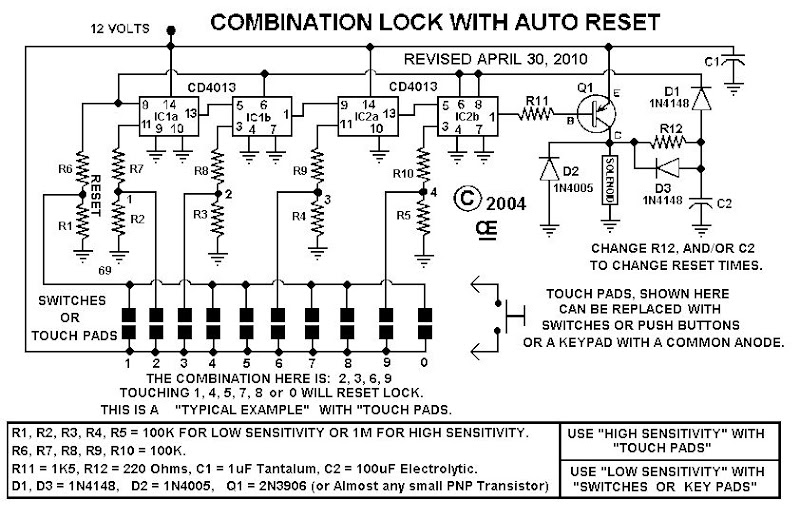
Combination Lock With Auto Reset


Combination Lock With Auto Reset
FEATURES:

9 to 15 Volt Operation. Can be used in a Motor Vehicle.

C-Mos Design, Low Standby Power.

4 Digit Enter Combination.

Unlimited Reset Keys, stops accidental entry by unwanted persons playing with &nbspit.

&nbspCan be used with "Touch Pads", "Push Buttons" or a Phone type "KeyPad". NOTE: High Sensitivity is NOT Required if using a "Keypad or Switches". &nbspSo the 1M resistors can be Reduced to 100K values if so desired. For Really High Sensitivity, the 1M Resistors can be increased to 8.2M or even 10M.

Optional "Auto Reset" after X number of seconds. (Eg: This causes the Lock to turn off "??" seconds "After the last number is &nbspentered") NOTE:&nbspIf you do not want this feature, leave off "R12", "D3" and "C2". &nbspAnd Changing R12 or C2 to higher values will increase this reset time. (On my Truck, I punch in the Combination and Immediately open the door before &nbspthe solenoid resets. It works great and no chance of leaving my truck unlocked.)

Further Info: The Circuit Board is Designed to accept 2 types of Drive transistors. I Used a 2N3906 in this schematic, but for Higher Current Drive for a Solenoid, You can use Various T0-220 PNP types of transistors. USE ONLY ONE OR THE OTHER, NOT BOTH. In the Picture, I just put a Resistor and LED, where the Solenoid should go.

Although Key Pads are Expensive, they do look nice. The Keypad I used was a Part Number 88AC2-162, Made by "Grayhill", But now its DISCONTINUED. Alternately Grayhill make others. Such a a 88AC2-172. Or go to www.grayhill.com to see what else is available.

Because this is a C-Mos design and Highly sensitive, it is "MOST IMPORTANT" to Remove All Traces of Solder FLUX from the board.

NOTE for a Touch Pad: Touch Pads can be easily made with 1/2 inch metal pads placed about 1/8 inch apart. This could be etched in Circuit board, but a material that doesn't oxidize would be better. Also they MUST be Protected from Water or it will Continuously "RESET", Stopping you from opening it.

Note: The Lock System on my truck is a Slightly different design than this circuit, but I use the Same Keypads on my truck and find they last about 10 years before needing replacing.

Inside my truck, I have a "Momentary Pushbutton" that supplies power directly to the solenoid. This is used to activate the solenoid and Exit the truck.

PARTS LIST

R1, R2, R3, R4, R5 = 1M or 100K R6, R7, R8, R9, R10 = 100K R11 = 1.5K OHM R12 = 220 OHM Q1 = 2N3906 C1 = 1 uF TANTALUM C2 = 100 uF ELECTROLYTIC IC1, IC2 = CD4013BCN D1, D3 = 1N4148 D2 = 1N4005 A Common Anode Keypad or Switches of some kind.
Read MoreCombination Lock With Auto Reset