Showing posts with label Microcontroller Circuit. Show all posts

PIC16F684 Digital Ammeter


The bellow circuit is digital Ammeter based on PIC16F684 and ACS712 current sensor. Here the measured ac/dc current will display on three digit 7-segment with resolution 100mA. In this project current sensor is ACS712ELCTR-30A-T . This circuit can measure the ac or dc current up to 30mA with 66mV/A output sensitivity.

The micro-controller PIC16F684 is used to read analog value from the ACS712 current sensor output and micro-controller convert to current and displaying on 7-segments display. For this circuit all 7-segment displays will be common anode type and it driven by PNP transistor BC557. Originally, this circuit is suitable for measuring DC current.
Read MorePIC16F684 Digital Ammeter

AVR microcontroller Based Ethernet Remote Switch Device


This baby Ethernet alien accessory opens a absolutely new apple of absurd applications. It's small, it's accessible to body and there are amaranthine possibilities to use it. Ethernet has commonly been a absolutely circuitous interface. All Ethernet chips until today had 100 pins or more, area difficult to acquisition in baby quantities and difficult to use from a baby microcontroller with little memory. Microchip has afflicted the apple with their new ENC28J60 Ethernet chip!

The ENC28J60 is a baby dent with 28 pins alone and has a SPI interface which is accessible to use from any microcontroller.This opens a accomplished apple of absolutely new applications. You can calmly body baby accessories which can be advance all over the abode and artlessly affiliated to ethernet.

You don't charge anymore a abstracted consecutive affiliation or added bus. Everything can be calmly affiliated via Ethernet. Distance is no best a attached factor. Even WIFI connectivity is accessible because you can affix the accessories to a wireless bridge.

Read MoreAVR microcontroller Based Ethernet Remote Switch Device

ISP Flash Microcontroller Programmer


Introduction

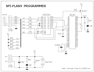
This ISP Programmer can be used either for in-system programming or as a stand-alone spi programmer for Atmel ISP programmable devices. The programming interface is compatible to STK200 ISP programmer hardware so the users of STK200 can also use the software which can program both the 8051 and AVR series devices.

https://blogger.googleusercontent.com/img/b/R29vZ2xl/AVvXsEgDRtYz7XIll7bOoq2F0vUB2qcLtGmTmZ4GbGDfwi4bZGNzN4XrJrldwcNFVhb_Xy92PkljOAdkxehmtKkBpFZIuPcGP0zewWyh8pHyeyK2cQx90lNOSvFLJyWUmaR0u2XQlorFUY_fMw/s320/isp2_sch.gif

Hardware

Figure 1 shows the circuit diagram of the in-system programmer interface, the power to the interface is provided by the target system. The 74HCT541 ic isolate and buffer the parallel port signals. It is necessary to use the HCT type ic in order to make sure the programmer should also work with 3V type parallel port.


More information (PCB, descriptions, Programmer software can be found at the following Link)
Link to main site
Read MoreISP Flash Microcontroller Programmer

Mini LOGGER V1.0 Block Diagram


Mini LOGGER V1.0 Block Diagram

Features of the MiniLOGGER V1.0 are as follows:

# Analog input: 8-channel single-end -99mV to + 999mV
# Analog-to-Digital Converter: integrated type converter, CA3162, with 1mV resolution at 4Hz sampling rate
# Pulse input: 1-channel TTL input
# Memory: battery backup SRAM 628128x2, 256kB (using MAX691 and +3V Lithium battery)
# RTC: battery backup DS1202
# Interval between sample: 10s to 600s
# Serial port: 9,600 baud for uploading the records
# Manual start/stop recording for standalone use
# Automatic start/stop recording with clock setting for daily measurement, say start 06:00 and stop 18:00
# Direct connected to WWW server for remote data retrieving
# ASCII formatted record for easily importing to EXCEL or any Scientific Plot Program

A simplified block diagram of the MiniLOGGER is shown in Figure 1. The CMOS analog multiplexer, 4051 provides the output for 8-channel single-end input to an analog-to-digital converter chip, CA3162. The CA3162 is connected in free running mode. The digital output is 4-bit BCD started with MSD, NSD, and LSD. The pulse period of MSD is 2ms. The 89C2051 runs solar3.hex, the firmware that controls 8-channel reading and receives external pulse. When the chip was triggered by INT0 signal, it will send the digital value in ASCII format through TxD pin;

*20819004722513922007403400000015

The format is in short form started with * then analog channel 0, 208mV, channel 1, 190mV and so on. The number 000000 is number of pulse input.

The 89C55 reads such record with time stamped read from DS1202 and saved into SRAM. Now it saves also DATE/TIME and provides comma for each channel separation.

26/12/99,22:16:24,208,190,047,225,139,220,074,034,000000

There's also a supervisory and power supply chip, MAX691 for battery backup to SRAM and RTC, MAX232 for RS232 converter, and ICL7660 negative voltage converter.
Read MoreMini LOGGER V1.0 Block Diagram