I connected the 2.4 GHz module from the Futaba transmitter T6EXP on the LS-jack on my Multiplex Royal Evo 12th The module transmits seven channels. It works easily and transparently as an RF module of the Evo.
Meanwhile, I have developed a second adapter for connecting to the Multiplex Cockpit SX and used for a microcontroller. Also for the Evo I now use an adapter with a microcontroller. See 'FASST module (2.4 GHz) to traditional broadcasters, Part 2'.
This modification, I do not want to advertise, but only report what I did and why. Because of the security risk, which means a transmitter failure, the adapter should only be built and used by people who are familiar with electronics. Who does that, it does at your own risk.
I was largely based on information that has found Rudy Fiala. He also called attention to the fact that the Futaba R606FS is actually a 7-channel receiver - it only lacks a connection.
Three steps were needed to equip the Evo with FASST and establish a fail-7-channel connecting to 2.4 GHz with the R606FS:
First, the receiver: I have added the small 220-ohm resistor, which is missing the connector for the seventh channel. See picture. Who manages with six channels can use the R606 unchanged. The RF module also works well with the R607, which contains the resistance at the factory, R617 and its successor.
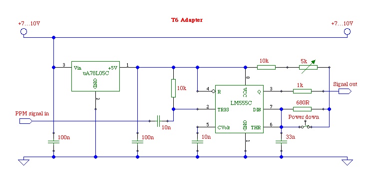
Secondly, the RF module: It sits as a piggy-pack on a slightly larger board, which also carries the status LEDs, the LS-connection and a 5-volt voltage regulator. If you turn around the board and look at the solder side, you see four wires leading to the left side of the board and three on the right side. The four left to go only to the LS-cable connection, they can be removed. The three right cables lead the mass, Battery Plus and the PPM signal from the main part of T6. The signal package consists of a PPM usual format with a cycle time of 22.5 ms, an amplitude of 3.3 V and start pulses to high level. The RF module can be adapted to virtually every PPM signal with up to eight channels. As a suitable adapter, such a pulse shaper:
Third, the connection to the socket of the LS-Evo: Pin4 leads the PPM signal with start pulses to low and an amplitude equal to the battery voltage. Power supply is on pin2 of the LS-jack. Mass is on pin 3. The plug must be a bridge between pins 3 and 5 lay, thus making the built-in RF module, the Evo off and brought out the PPM signal on pin 4.
The adapter circuit is experimented on various channels (such as MPX 3030, 4000, Graupner MC-22). The input signal (signal in PPM) is the PPM data stream, which is available on the LS-connection. The polarity of the signal does not matter, the amplitude should be at least 3V. The supply voltage (about 7V ... 10V) can also be obtained from the LS-connection, it is passed to the carrier board of the RF module, which is located on the 5V regulator. the switches' power is down "open, the RF module is running in low-power mode in order to reach test. This mode should not be used in normal operation.
The adapter forms a PPM data stream with positive start pulses, as required by the FASST transmitter him. Different lengths of the start pulses switch the transmitter to different modes. In T6EXP only vary the lengths of the first two start pulses, but it obviously makes no difference if all pulse lengths can be changed in the same way. These are the pulse lengths and related modes, as published by Stephan RCLine in the forum:
400 microseconds: Regular operation without Failsafe
420 microseconds: Regular operation with failsafe on channel 3, and fail-safe position is transmitted on channel 8.
440 microseconds: Power-down mode to reach test.
The adapter circuit for the first time must be trimmed. When the switch is open, I put the trimmer so that the RF module goes into power-down mode (green LED and red LED flashing). Then there is by closing the switch over to regular operation, including offset Failsafe (green LED on, red LED off). On the Evo I use channel 3 as a motor channel, because the offer FASST Receiver R606, R607 and R617 only for the channel, the fail-safe function. The fail-safe position "motor off" is transmitted on channel 8. I have it on the transmitter a fixed value of -100% on channel set 8th In the second part presented a microprocessor-based adapter, this setting is not needed because the adapter itself creates a fail-safe signal.


