Description
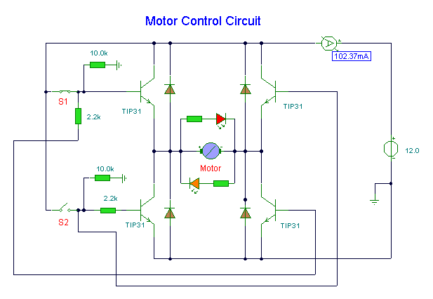
This circuit uses solid state switching (transistors) to control direction of a DC motor. You have precise control of the movement of the motor, and an indication of direction provided by LED's.
Circuit Notes:
Switches S1 and S2 are normally open push to make, press button switches. The LED's serve to indicate direction and may be any colour. You may need to alter the TIP31 transistors depending on the motor being used. Remember, running under load draws more current. This circuit was built to operate a small motor used for opening and closing a pair of curtains. This circuit allows manual control of the motor (and for curtain control) allows precise amounts of light into a room.
The four diodes surriunding the motor, are back EMF diodes. They are chosen to suit the motor. For a 12V motor drawing 1amp under load, I use 1N4001 diodes.
Via


