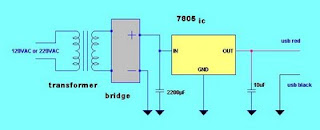
This DIY simple iPod Charger Project aims to give simple idea on how to build you IPod charger and explain in details the materials needed and their functions. This page will serve as a guide on constructing the charger. Schematic diagram of the is shown below. The IPod charger circuit is composed of an AC to DC converter and a voltage regulator.
Requirements of a good iPod charger
For the iPod battery to be charged well and safely, we must come up to a battery charger design that is similar to commercial IPod charger specifications. The charger output voltage is about 5V of about maximum current of 800mA
Charger materials and their functions
Transformer (step down) - is used to step down the voltage from an input voltage of 220VAC to 12VAC output or you can use 120VAC to 12VAC if you have 120V main source. Transformer is rated 5VA
7805 regulator IC -7805 regulator IC that will maintain the voltage output to 5V for good and safe charging of IPod battery. You can use any voltage 5V regulator IC that is available.
Diode Bridge or Rectifier Diode – this is where the conversion of Alternating Current (AC) voltage to Direct Current (DC) takes place. DC voltage is needed for battery charging.The bridge diode must be rated 1A.You can chose any of the rectifier below.
W02M- 1.5A 100V Bridge Rectifier
1N4001 -1A 50V
or any diode of the same specs
Capacitor –It minimize fluctuating voltage (ripple voltage) coming from the bridge rectifier. Provides better voltage regulation in the charger
2200uF 25V capacitor or higher
10uF 10V capacitor or higher
Female end of USB connector- is where the charger cord is connected and the IPod is charged. Use only the RED (1) and BLACK (4) for the charger circuit.
pin 1 red -is connected to the positive output of IPod charger (5V)
pin2 white- data wire, no connection
pin3 green- data wire, no connection
pin 4 black -is connected to ground or negative output of Ipod charger
pin2 white- data wire, no connection
pin3 green- data wire, no connection
pin 4 black -is connected to ground or negative output of Ipod charger
use only pin 1 and pin 4 for this charger
Miscellaneous charger accessories
Wires
Cutter for cutting wires
Voltmeter for testing the output
Steps in IPod charger construction
1. Prepare the needed materials
2. Assemble the circuit by following the circuit diagram
3. Test the charger output voltage by a voltmeter-It must be 5V DC
Via: electronician.blogspot.com


